Rishi kumar shukla et. A connecting rod consists of a pin-end a shank section and a crank-end as shown in Figure.
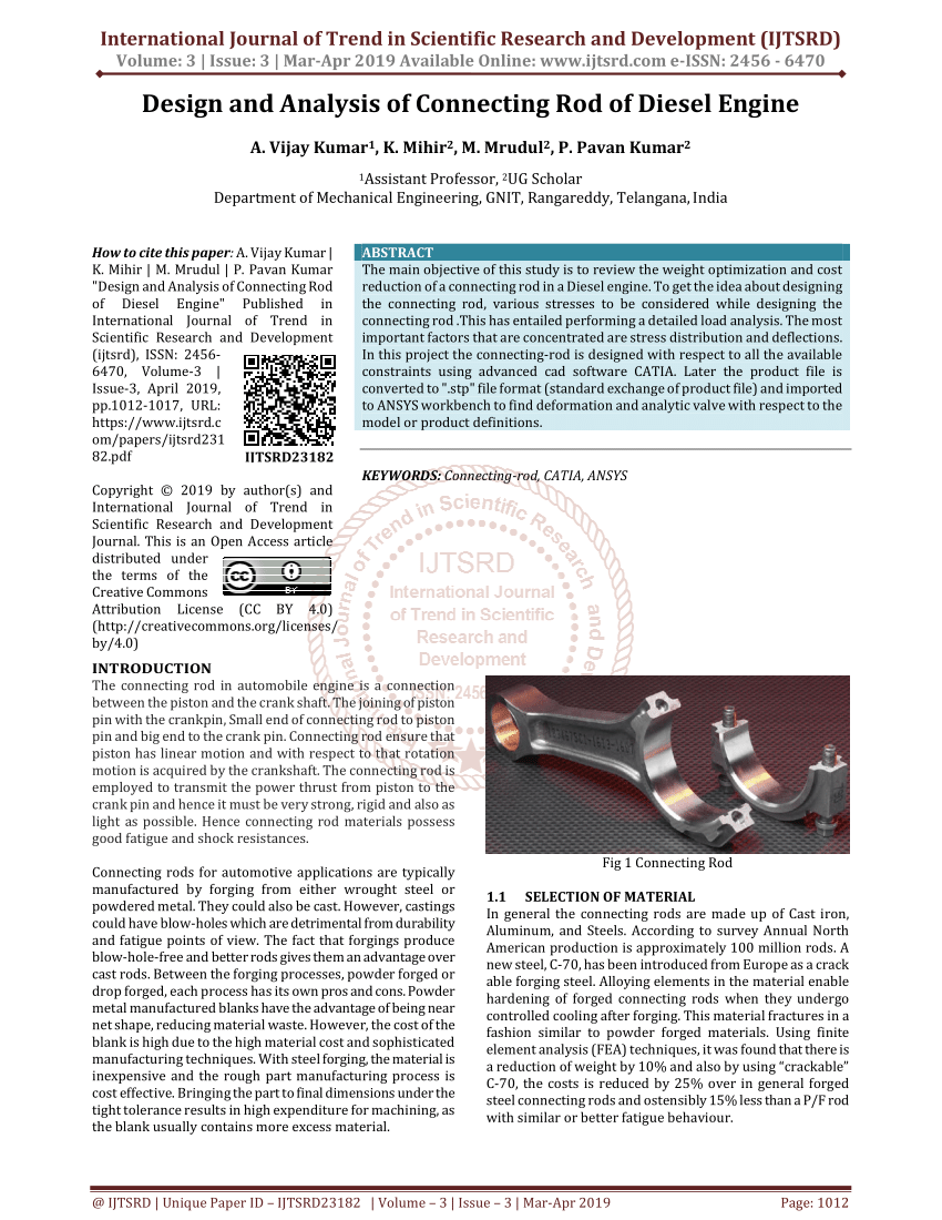
Pdf Design And Analysis Of Connecting Rod Of Diesel Engine
Ilia et al 2005 provide the minimum I-beam area for the connecting rod for the 19 L and 22 L engines as 132 mm 2 and 141 mm 2.
. It connects reciprocating piston to rotating crankshaft. The connecting rod is considered like both ends hinged for buckling about x-axis and both ends fixed for. Ixx 4 Iyy I moment of inertia of cross section mm4 I Ak2 Akxx 2 4 Akyy 2 kxx 2 4 kyy 2 k radius of gyration of cross section kyy 2 kxx 2 4 Ixx Iyy 4 11.
As tolerance chain analysis is an. Hello friendsHere in this video we will learn about the design procedure of Connecting Rod which is a part of internal combustion engine. Due to Cap tight problem in the connecting rod there will be loss of time for separate the cap and due to oversize of big end diameter of connecting rod there will be both wastage of time and material.
The Connecting rods are usually made of. L connecting rod length centre to centre 122mm ω 6500 rpm 2π60 680678 rads Therefore The mass of the part in question is calculated by summation of the little end components ie. Dimensions of cross-section of the connecting rod Connecting rod should be designed in such a way that it is equally resistant to buckling in either plane.
The lower end also called as Big end is attached to the crankshaft. We pride ourselves on our ability to be innovators of cutting-edge honing technology. Designs of connecting rod have been analysed in this report and finally an optimal design has been selected using ANSYS-145 Workbench and CATIA V5.
These holes must be parallel. The connecting rod is a component that is subjected to the axial compressive force which is equal to the maximum gas force acting on the piston. In this design process the first step is to determine the engine cycle parameters.
That is in any internal combustion engine with the help of it the reciprocating motion is converted to rotary motion. The optimization of this process is. The step by step procedure for designing of the connecting rod using design data hand bookDesign data hand book by Mahadevan.
Connecting rod Structural analysis Titanium Steel Gas load Fatigue FEA 1. Hence the design of the connecting rod is as a column or a strut 1. During its lifespan it faces a lot of tensile and compressive loads.
Then the cylinder compression and expansion processes are calculated. They are used respectively depending on their field of application or use. Finite element modeling and analysis were performed using MSCPATRAN and MSCNASTRAN software.
Connecting rod must be sufficiently strong to withstand the thrust from the piston during the combustion process. The design of connecting rod is checked and analyzed. The small end is press fit and can swivel in the piston.
This paper presents the design connecting rod of internal combustion engine using the topology optimization. The structure of connecting rod was modeled utilized SOLIDWORKS software. From tool and fixture design through machine design engineering and manufacturing to process development metrology final run-off automation packages IIoT and secure remote monitoring and in-field support.
In the one by Takemasu et al. Pin-end and crank-end pinholes at the upper and lower ends are machined to permit accurate fitting of bearings. We deliver machines tools and automation.
Connecting rod The connecting rod links the piston and the crankshaft. This project aims at designing a connecting rod with standard dimensions of a stock one in CREO 30 software and analyze the design using designing software ANSYS. The upper end of the connecting rod is connected to the piston by the piston pin.
Connecting Rod Rectangular and I-Beam Cross-Sections With the assumed shape of the cross section for the connecting rod as shown in Figure 2b the cross sectional area of the I-beam section is 11 t 2. The piston and rings the gudgeon pin the bearing shell and the top of the connecting rod. A MaximumCylinderPressure C F C MaxCylP A 9u 4418 39762 2 2 4418 4 75 4.
Being one of the most integral parts in an engines design the connecting rod must be able to withstand tremendous loads and transmit a great deal of power. Connecting rods are manufactured by means of forging. For buckling the connecting rod is four times.
6 the objective is to design the forging process of a connecting rod with no flash in order to save costs. This thesis has been focused on the study of the connecting rod manufacturing process. The objectives of this paper are to develop structural modeling finite element analyze and the optimization of the connecting rod for robust design.
The objectives of this paper are to develop structural modeling finite element analyze and the optimization of the connecting rod for robust design. Failure of a Connecting Rod IVTHE DESIGN PROCESS. International Journal of New Technologies in Science and Engineering Vol.
Finally is to. A connecting rod subjected to an axial load W may buckle with x-axis as neutral axis in the plane of motion of the connecting rodor y-axis is a neutral axis. The connecting rod and the piston changes as the rod moves up and down and rotates around the crankshaft.
The structure of connecting rod was modeled utilized SOLIDWORKS software. To this end it is necessary to finely control the volume and geometry of the preform in order to avoid both the flash appearance and the incomplete die filling. So we do some study on the design and manufacturing process of connecting rod to understand the reason of this two problem.
An I-beam is both light. Ignore the little friction between the piston and the cylinder and the connecting rod the design as long as the research and analysis of gas pressure and inertia force. Section of the connecting rod is designed as a strut and the rankine formula is used.
In the design requirements of the rod. It has a hole at the upper end small end and is connected to the piston by the wrist pin. One of the important part of the combustion engine is the connecting rod and the main purpose of the connecting rod is to transfer the energy from.
The analysis of the Scania line together with a benchmark among different leading companies on the connecting rod manufacturing has been undertaken. INTRODUCTION A connecting rod can be of two types H-beam or I-beam or a combination of both. If the piston pin is.
The pull and push in the piston receive the piston pin then the connecting rod acts as the transfer of the pull and pushes from the piston pin to the crank pin. The compressive stress is of significant magnitude.

Pdf Design Analysis And Optimization Of Various Parameters Of Connecting Rod Using Cae Softwares Semantic Scholar
Pdf Design Considerations For Connecting Rod

Pdf Design And Comparative Analysis Of Connecting Rod Using Finite Element Analysis

Pdf Design And Comparative Analysis Of Connecting Rod Using Finite Element Analysis
Pdf Design And Analysis Of A Connecting Rod
Pdf Design And Analysis Of A Connecting Rod For The 117kw Six Cylinders Turbocharged Diesel Engine

Pdf Design Analysis And Optimization Of Various Parameters Of Connecting Rod Using Cae Softwares Semantic Scholar

U3 Design Of Connecting Rod I Section Big Amp Small Eng Bolt Whip
0 comments
Post a Comment